
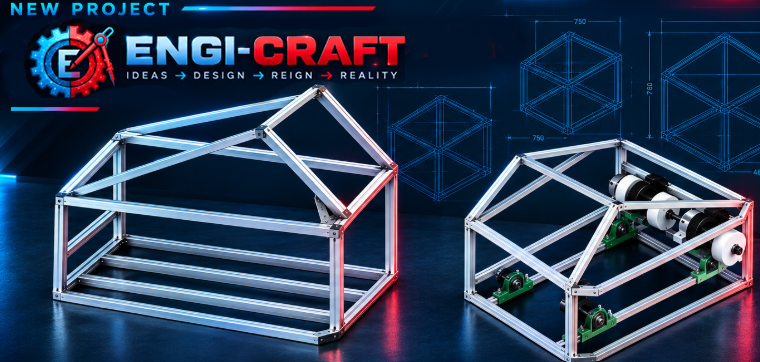

Work on the heavy-duty remote-controlled utility platform (RC Utility Robot) is kicking into high gear! From day one, this machine was conceived as a rugged, workhorse chassis designed for tough winter conditions—specifically high-load snow removal and heavy-terrain payload hauling.
To withstand these operating stresses, I opted for uncompromising mechanical solutions paired with reliable drive electronics and power storage.
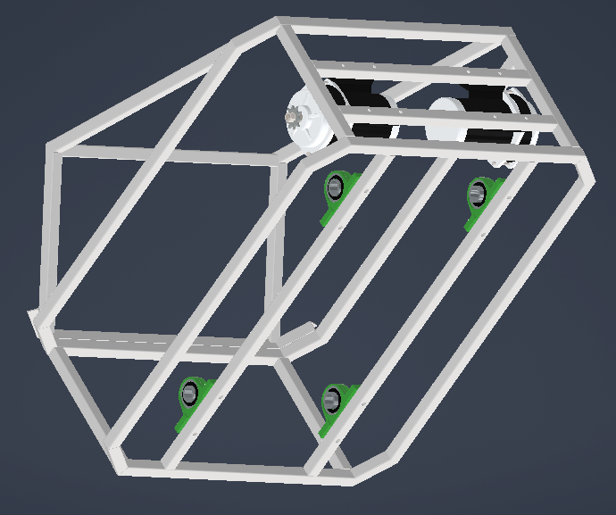
1. 3D Modeling in Autodesk Inventor – Early Concept Phase
Before cutting the first steel profile in the workshop, the overall geometry and drive kinematics were mapped out in CAD. The early modeling phase in Autodesk Inventor allowed me to verify wheelbase dimensions, evaluate plow linkage geometry across multiple articulation angles, and estimate preliminary weight distribution to maintain optimal downforce on both front and rear axles.
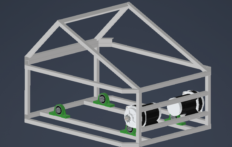
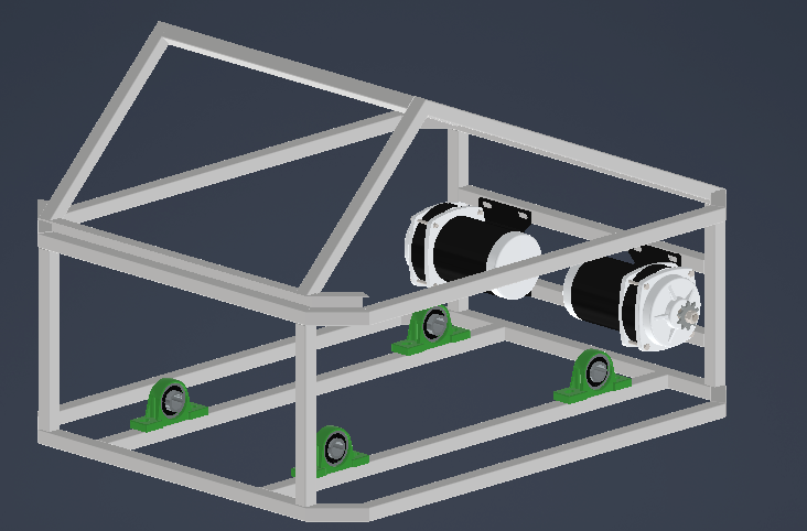
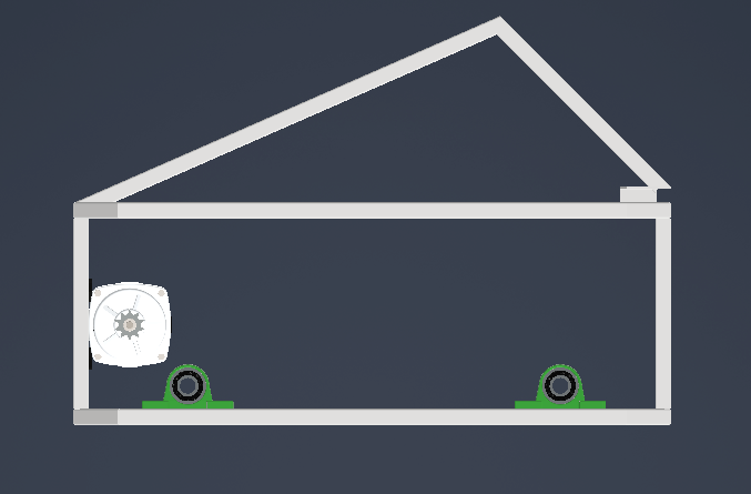
2. Drivetrain & Mechanics: 24V, Dual Sprockets, and Serious Torque
The core drive system relies on two powerful brushed 24V 500W DC motors.
- Primary Gear Reduction: A 6:1 gear reduction yields roughly 12 Nm of torque directly at each motor output shaft, providing plenty of low-end grunt when starting under heavy load.
- Final Drive: Torque transfers from the gearbox shafts to the drive wheels via a heavy-duty roller chain and twin sprocket setup. The chain drive ensures maximum shock absorption and resistance to severe stall loads in mud or heavy snow, completely eliminating the slipping risks associated with timing belts.
- Working Implements: Plow height and angle adjustments are actuated by 12V linear actuators, offering precise positioning and holding force against packed snow.
3. Drive Electronics – Partnership with Cytron Technologies
Safely managing high stall currents and aggressive dynamic braking required professional motor controllers. For this build, I partnered with Cytron Technologies to supply the drive electronics:
- Dual-channel high-power drivers from the SmartDriveDuo lineup (Cytron Technologies) handle steep peak current demands with ease. They come equipped with built-in thermal and overcurrent protection, along with native support for mixed RC inputs (skid-steer tank mixing).
4. Energy Storage – Partnership with WattCycle (Built-in Winter Self-Heating)
Sub-zero temperatures and high transient draw represent a serious challenge for standard lithium chemistries. As part of a collaborative setup with WattCycle, the robot is powered by dedicated LiFePO4 battery technology:
- The packs from WattCycle feature built-in automatic cell heating (Self-Heating).
- This is a critical feature for winter service: charging standard LiFePO4 below freezing causes irreversible damage through lithium plating on the anode. The integrated heating pads allow the BMS to safely warm the cells above 0°C before accepting a charge, while enabling full discharge output and stable voltage even in bitter frost.
- Combined with thousands of charge cycles and robust cell chemistry, this power unit provides a virtually maintenance-free electrical backbone.
5. Control System & Ancillary Equipment
- RC Transmitter/Receiver: Vehicle handling relies on the reliable FlySky FS-i6X radio setup, providing proportional skid-steer throttle response, dedicated channels for actuator control, and auxiliary mode switching.
- Auxiliary Work Lighting: High-output LED light pods are mounted to the chassis, ensuring full visibility during early morning and late night snow clearing operations.
- Multi-Voltage Power Distribution: The onboard system integrates the primary 24V power bus (main traction motors) with high-efficiency step-down converters powering the 12V linear actuators, work lights, and radio receiver.
6. Current Build Status: Welded Chassis & Next Workshop Milestones
Moving from the virtual screen to the fabrication table, the main structural chassis is now fully welded. The frame provides extreme torsional stiffness, though a few preparatory steps remain before assembling the mechanical drive components.
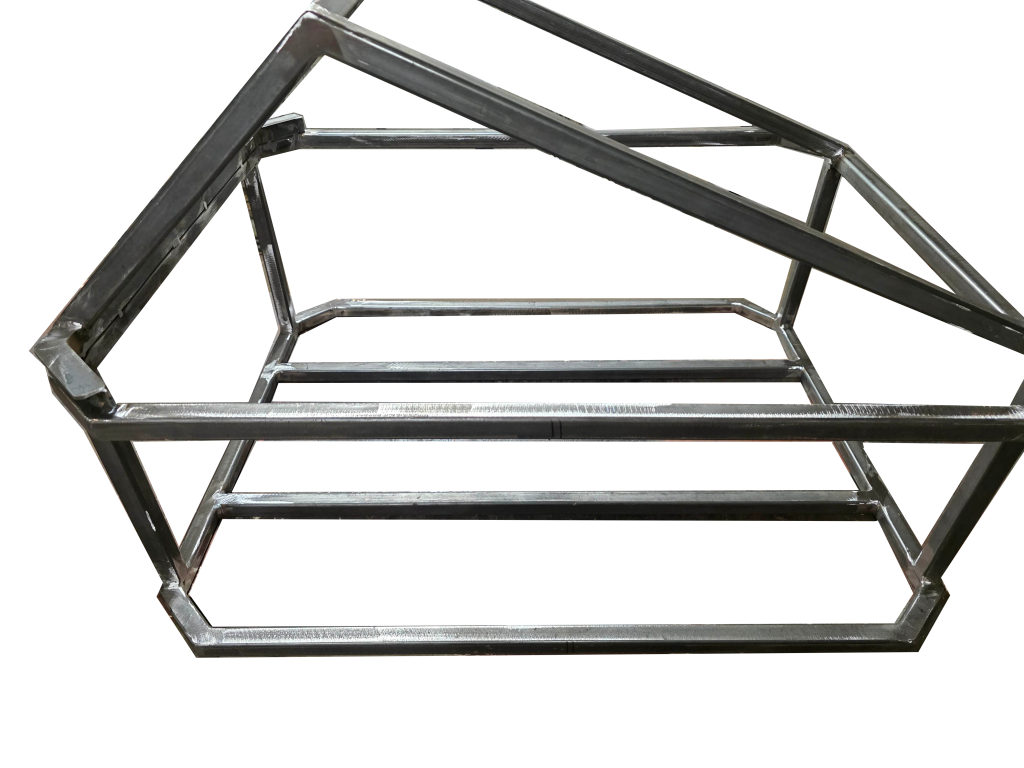
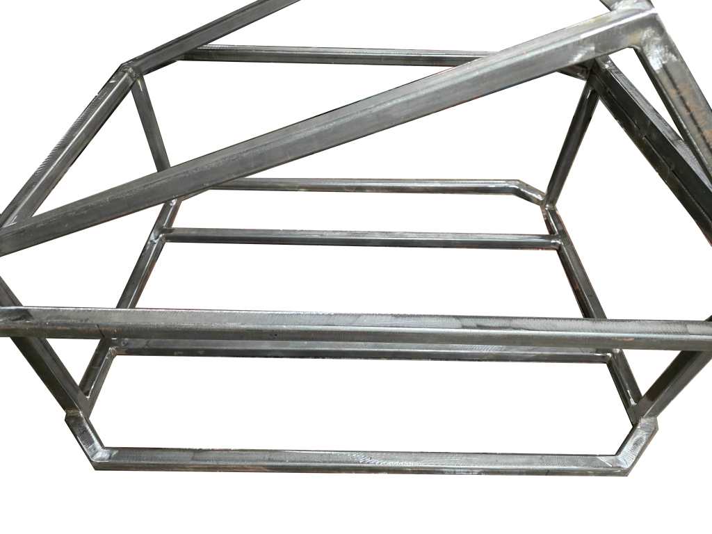
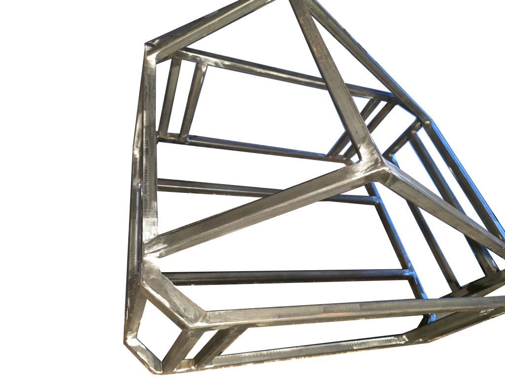
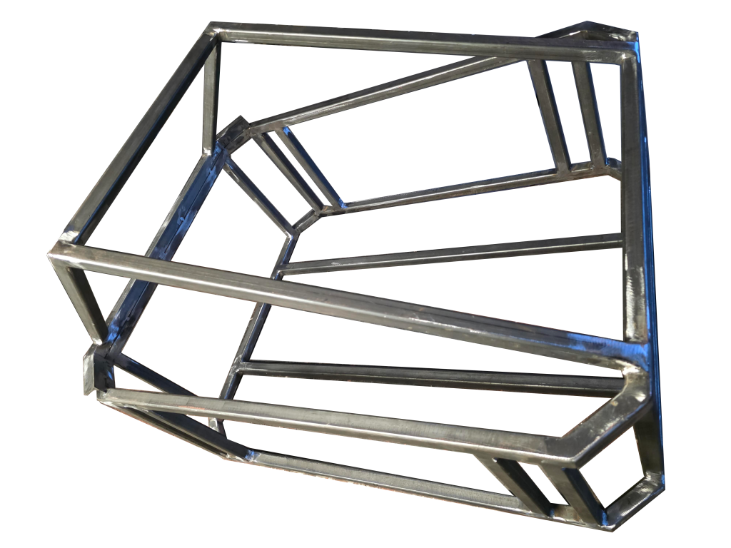
The chassis is currently staged for weld dressing and initial surface cleanup. The immediate next steps include:
- Marking out and bolting down the pillow block bearings within the frame geometry,
- Calculating precise axle shaft lengths and machining steps, accounting for chain sprocket alignment and wheel hub spacing.
Engineering Inspiration: Filtered Through Calculations
A build like this was certainly inspired by an overseas DIY developer working on similar utility robots. However, I made a conscious effort never to replicate someone else’s blueprints blindly.
Every overall dimension, profile cross-section, gear ratio, and raw component choice was run through my own engineering checks. I recalculated frame weld stresses, evaluated horizontal plow reaction forces, and tailored the entire footprint to my available workshop equipment, regional steel profiles, and target working conditions. Every joint in this chassis has a calculated reason to be there.
Coming Up Next
This is just the first part of the build series. In the next update, we will break down every single component:
- A complete bill of materials covering hardware, electrical parts, and fasteners,
- Individual close-up photos of each component alongside its technical specs and material selection rationale.
Stay tuned—the fabrication work is moving fast, and dynamic mechanical assembly begins shortly!